Before we get into the BeagleBone AI-64’s TDA4VM, let me start with something more personal.
The first microprocessor I ever worked with was a Z80. It wasn’t soldered onto a PCB or hidden under a heatsink. Instead, it sat fully exposed on a breadboard, with the address bus, data bus, control lines, and all the glue logic wired right in front of me. You could actually see the machine, touch it, and follow the signals with your finger. That hands-on experience with the low-level world shaped the rest of my career.
Later, when I studied Control Engineering and worked on the automotive “Automatic clutch Project“, the concepts of “real-time” and “safety” became more than theory. They became something you could feel in your bones: deadlines, jitter, timing, determinism, stability. And that same curiosity that started with “how does this bus actually work?” naturally evolved into “how does a modern SoC handle real-time inside a Linux system?”
That’s why whenever I hear “real-time” or “safety” mentioned with “Embedded Linux,” I pay close attention. Linux is an excellent general-purpose OS: powerful, flexible, and mature. But expecting it to deliver strict real-time behavior, even with PREEMPT_RT and every patch available, is optimistic. Linux isn’t built for deterministic microsecond response, and that’s okay. It doesn’t need to be.
So the real question becomes: where do the real-time parts of a modern embedded system actually live? That brings us to the present.
When you first boot a BeagleBone AI-64…
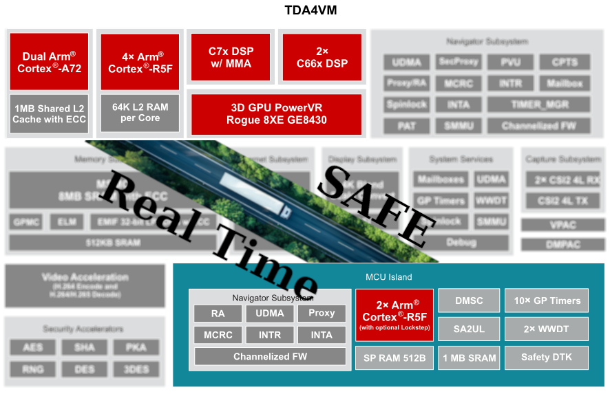
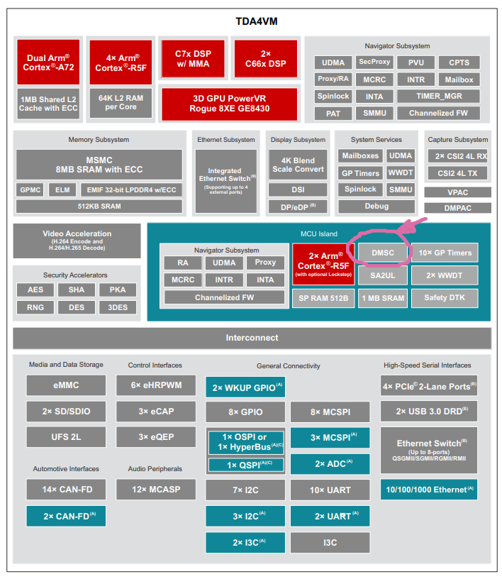
When you first boot a BeagleBone AI-64, it’s easy to think of it as “just another ARM board running Linux on some Cortex-A cores.” But under that Debian userland, there’s a much more interesting SoC hiding: TI’s TDA4VM, with multiple Cortex-R5F cores sitting next to the A72 cluster, ready for real-time and safe work.
In this post, I’m sharing notes, logs, and experiments from bringing up bare-metal firmware on one of those R5 cores and turning them into a guide you can follow and reproduce. There’s no magic or black boxes here, just a clear path from “ELF won’t load” to “Linux is talking to R5 over RPMsg.”
First, I’ll give you an overview of the architecture and the mental model:
What hardware is available, how Linux exposes the R5 cores, and the different ways Linux and the firmware can communicate. Later parts will cover details such as linker scripts, remoteproc errors, and bringing up a sample ELF file on R5.
Part 1:The Hardware in Plain Terms: TDA4VM on BeagleBone AI-6
The BeagleBone AI-64 uses TI’s TDA4VM, a heterogeneous computing platform. (BeagleBone AI-64 Overview, n.d.) Simply put, you can think of it as:
- A Cortex-A72 cluster where Debian Linux runs and does “normal computer things”: processes, networking, filesystems, userspace tools, etc.
- Cortex-R5F cores are designed for deterministic, low-latency real-time work. In the TDA4VM, some of these R5Fs are used to implement the MCU Safety Island with functional-safety (ASIL-D) capabilities, and depending on system configuration, some R5Fs may operate in lockstep pairs while others run independently.
- Additional DSPs and hardware accelerators we’re not using in this document, but many follow a similar “separate memory, separate firmware” model, though System Firmware rather than Linux controls some.
For the R5, the key point is that each R5 runs in its own dedicated execution environment, isolated through TCM and DDR carve-outs, with additional isolation enforced by firewalls on the shared interconnect. (TCM is available to the core, but remoteproc typically maps only the DDR carve-out unless the device tree includes TCM regions.)
The remoteproc loader and the SoC firewalls together prevent the firmware from accessing memory outside the reserved carve-out. Linux exposes each controllable R5 core through the remoteproc framework. This framework loads an ELF file into the right carve-out, sets up shared resources, and starts the core.
During my experiments, I had three R5 remoteprocs visible. One was already “attached” (reserved by System Firmware / TIFS), so I ignored it. The other two were available for custom firmware, and those became the playground for everything documented here.
The architecture is straightforward: Linux handles complex, high-level logic, while the R5 cores run tight loops, safety-critical control, or low-latency processing. They work side by side, but remain separate.
How Linux Sees the R5 Cores: Remoteproc in Practice
On a running BeagleBone AI-64, Linux exposes the R5 cores that System Firmware does not reserve under /sys/class/remoteproc:
- each R5 appears as remoteprocN,
- has a name, state, and firmware attribute,
- and is bound to a specific reserved memory region defined in the device tree.
The remoteproc framework acts as the supervisor. When you ask it to start an R5 with a firmware image, it doesn’t just run it without checks. (NXP MPU Cortex-A Core Zephyr User Guide, 2025) Instead, it:
- Parses the ELF headers.
- Checks every loadable segment (PT_LOAD) and verifies that it fits entirely inside the R5’s reserved DDR carve-out from the device tree.
- Look for a .resource_table section that describes shared memory, trace buffers, virtio devices, and RPMsg vrings.
- Allocates any resources the table asks for.
- Copies code and data into memory.
- Finally, release the R5 out of reset.
If any segment is even one byte outside the carve-out, remoteproc rejects the firmware with an error like:
bad phdr da 0xa6100000 mem 0x8c
This is not just an “oops”; it’s the kernel telling you your linker script and your device tree carve-out disagree on the memory map, and it will not risk running that firmware.
The key takeaway is that your linker script, ELF, and DTS carve-out must all match. Once they do, remoteproc becomes a reliable and predictable loader.
The Memory Story: Carve-Outs and Linker Scripts
Each R5 remoteproc instance is paired with a reserved-memory region in the device tree. You see them show up in the boot log as things like:
r5f-dma-memory@a2000000That tells you the starting physical address of the carve-out (here, 0xA2000000) and implicitly the size and purpose.
Your R5 firmware’s linker script must:
- place the resource table in that region,
- place any shared DDR buffers (like the log buffer) in that region,
- and ensure that no loadable segment spills outside.
In my first attempt, the linker script had:
__DDR_START__ = 0xA6000000;Which led to a segment trying to live at 0xA6100000. But the carve-out for that remoteproc started at 0xA2000000, so the kernel quite correctly rejected it as having a bad phdr.
After changing the linker to:
__DDR_START__ = 0xA2000000;And rebuilding, everything suddenly started working: remoteproc accepted the ELF, the R5 booted, and the shared trace buffer became visible.
If you remember one thing from this section, let it be this: your linker script is a contract with the kernel’s reserved memory. If you get that contract right, the rest of the bring-up process is much easier.
How R5 Talks to Linux: Communication Models
Once the firmware boots, the next question is how the R5 core and Linux userspace communicate.
On the TDA4VM and BeagleBone AI-64, you have several options. This document covers the details, but the main idea is:
- start with the simplest thing that gives you visibility (trace buffer),
- move to a structured message channel (RPMsg),
- and only then consider heavier patterns, such as custom shared memory or the full TI IPC stack.
Let me walk through the main ones in plain language.
Remoteproc Trace Buffer – the basic “Hello, am I alive?” channel
The trace buffer is the simplest and most important tool during bring-up.
On the firmware side, you define a global log buffer, place it in a special section (e.g. .log_shared_mem), and map that section into DDR in the linker script. The resource table tells Linux, “here is my trace buffer at address X with size Y.”
Linux then exposes it under debugfs as:
/sys/kernel/debug/remoteproc/remoteproc4/trace0The R5 writes text into that buffer. Linux reads it.
This is perfect for:
- confirming that main() actually runs,
- checking that the memory mapping is correct,
- dumping early diagnostic messages while you are still fighting with RPMsg.
It only works one way (R5 to Linux), but during initial bring-up, it’s extremely valuable.
RPMsg over virtio – the “real” Linux ↔ R5 message bus
Once the basics are working, you need proper bi-directional communication. That’s where RPMsg comes in.
In the resource table, the firmware declares a virtio RPMsg device and two vring devices. Linux sees that, allocates ring buffers for the vrings inside the carve-out, binds the virtio_rpmsg_bus driver, and creates /dev/rpmsgX devices. (Menon & Dhruv, 2024)
On the R5 side, the firmware creates an RPMsg endpoint and registers a callback. On the Linux side, you can write a small userspace client that:
- Opens/dev/rpmsgX,
- writes a fixed-format message,
- and reads the response.
In my setup, I used a very simple struct r5_msg containing:
- a magic number,
- a protocol version,
- a command ID,
- a sequence number,
- and a tiny payload.
The first command I implemented was PING, to verify that the round-trip path works end to end. After that, it was easy to add things like GET_STATUS and SET_PERIOD to read internal counters or change the firmware’s timing at runtime.
RPMsg is the best choice for most cases. It’s structured, supported by the kernel, and easy to use with both C and Python tools on Linux. (Remote Processor Messaging (rpmsg) Framework, n.d.)
Custom Shared Memory and Mailboxes – for when you need “serious throughput.”
Beyond that, you can go deeper:
- map a region of shared DDR and treat it as a manual circular buffer for high-bandwidth data,
- pair it with mailboxes/doorbells for low-latency event notification
- or sit atop TI’s IPC stack for higher-level abstractions.
These options give you better performance and flexibility, but they also demand greater engineering discipline: cache management, race conditions, state machines, and devicetree interrupt wiring are now your responsibility.
For the initial bring-up story in this series, I stick to the trace buffer + RPMsg. That’s more than enough to get a robust Linux ↔ R5 control plane in place.
Part 2:
From “ELF won’t load” to a Running R5 Core with Trace Output
In Part 1, we built the mental model — what the TDA4VM looks like internally, how Linux exposes the R5 cores, and how trace buffers / RPMsg fit into the picture.
Now it’s time to get our hands dirty.
This part is the exact bring-up path I used on the BeagleBone AI-64, distilled into a reproducible form. It includes the real error messages, the wrong linker script, the fix, and that magic moment when remoteproc finally says “remote processor … is now up”.
If you follow this post with your own board, by the end, you will have:
- A working Cortex-R5 bare-metal firmware
- Loaded via the Linux remoteproc subsystem
- Writing visible output into a shared trace buffer
That trace output is the “heartbeat” that proves your R5 is alive and executing your code.
Let’s get started.
1. Installing the Toolchain and Building the Firmware
The BeagleBone AI-64 runs Debian on the A72 cores, but the R5 firmware is built on a host machine. I used Ubuntu 22.04:
sudo apt install gcc-arm-none-eabi makeThen grab the example repository:
git clone https://github.com/kaofishy/bbai64_cortex-r5_example.git
cd bbai64_cortex-r5_example
make
The Makefile compiles test.c and links everything using a custom linker script (gcc.ld).
If the build succeeds, you get:
test.elfThis is your bare-metal R5 firmware.
If you’re curious:
test.c includes the vector table, the reset handler, a simple “Hello world” write into a trace buffer, and a minimal resource table so Linux knows where the shared memory and vrings would live.
We’ll explore those details in Part 3.
2. Copying the Firmware to the Board
On your host:
scp test.elf debian@<board-ip>:/home/debian/On the BeagleBone AI-64:
sudo mv /home/debian/test.elf /lib/firmware/r5_hello.elf
sudo chown root:root /lib/firmware/r5_hello.elfThe /lib/firmware directory is essential because remoteproc only loads files from this location.
3. Finding the Available R5 Cores
Linux exposes the R5 cores that are not reserved by System Firmware (SYSFW) through the remoteproc framework in:
/sys/class/remoteproc/Check what’s available:
for i in 3 4 5; do
 echo "remoteproc$i: $(cat /sys/class/remoteproc/remoteproc$i/name)";
 echo " state:      $(cat /sys/class/remoteproc/remoteproc$i/state)";
 echo;
doneOn my board, I saw:
- remoteproc3 → “attached” (reserved by system firmware)
- remoteproc4 → available
- remoteproc5 → available
For the rest of this series, we’ll use remoteproc4 as our test target.
4. First Attempt: “bad phdr” – The Classic Remoteproc Failure
Let’s try to boot the firmware:
echo r5_hello.elf | sudo tee /sys/class/remoteproc/remoteproc4/firmware
echo start | sudo tee /sys/class/remoteproc/remoteproc4/stateAnd… boom :
remoteproc remoteproc4: bad phdr da 0xa6100000 mem 0x8c
remoteproc remoteproc4: Failed to load program segments: -22
remoteproc remoteproc4: Boot failed: -22
This is the kind of moment that often makes people give up on R5 bring-up, but once you understand it, it’s actually very clear.
What happened?
- The ELF contains several PT_LOAD segments.
- Remoteproc checks whether each segment fits within the reserved-memory carve-out defined in the device tree.
- For remoteproc4, the carve-out starts at:
r5f-dma-memory@a2000000But the ELF wanted to load a segment at:
0xA6100000That’s outside the allowed region → kernel rejects the ELF.
The cause?
A wrong DDR base address in the linker script:
__DDR_START__ = 0xA6000000; //wrongThis one line causes remoteproc to reject the entire firmware.
5. Fixing the Linker Script
We correct it:
__DDR_START__ = 0xA2000000; // matches r5f-dma-memory carve-out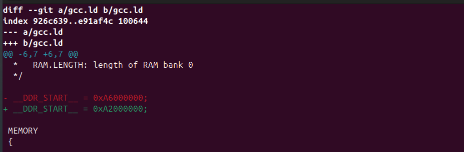
Rebuild:
make clean
makeCopy the new ELF back to the board, update /lib/firmware/r5_hello.elf, and start again.
6. Success: The R5 Boots and Comes Alive
This time, the kernel log shows:
remoteproc remoteproc4: powering up 5c00000.r5f

remoteproc remoteproc4: Booting fw image r5_hello.elf, size 89028

rproc-virtio rproc-virtio.4.auto: assigned reserved memory node r5f-dma-memory@a2000000

virtio_rpmsg_bus virtio1: rpmsg host is online

remoteproc remoteproc4: remote processor 5c00000.r5f is now up
This is the key moment. Remoteproc validated the ELF, mapped the resource table, allocated vrings, and released the R5 core from reset. You can confirm the state:
cat /sys/class/remoteproc/remoteproc4/state
runningAnd check the trace buffer:
sudo cat /sys/kernel/debug/remoteproc/remoteproc4/trace0You should see:
Hello world!
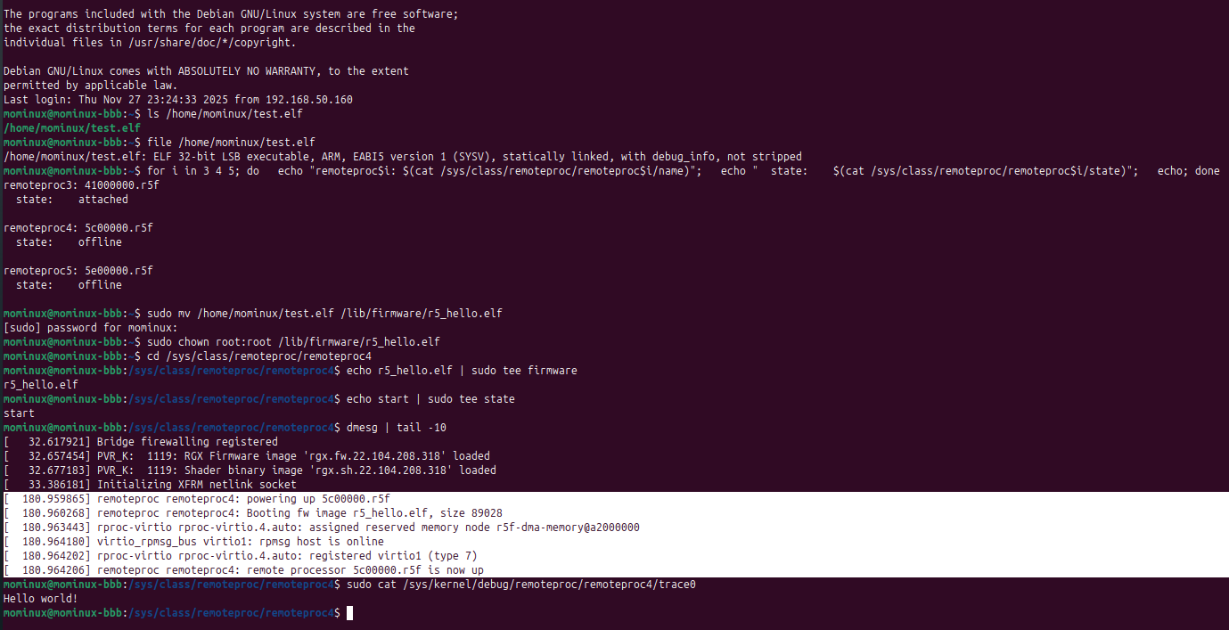
That message shows the R5 core is successfully writing into a DDR buffer that Linux exposes. It’s the firmware’s first sign of life.
That’s enough for tonight, let’s get some sleep. Next time, we’ll jump into the code and see what other tricks we can use to talk to the R5.
Reference:
1- Texas Instruments documents and application notes
2- https://github.com/kaofishy/bbai64_cortex-r5_example.git